

Repair Kit
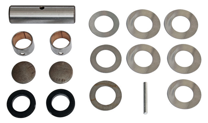
1949-1954 Chevrolet Passenger Idler Arm Repair Kit. Replaces GM# 3696372. Includes: pins - bushings - shims - retainer - seals and dust caps. SEE A VIDEO ON HOW WE REBUILD THESE IDLER ARMS: Click here to view A worn out steering idler arm on 1949-1954 Chevy passenger cars can negatively affect steering accuracy. It is one of the most common steering issues on these cars. Lack of proper lubrication is the main cause of idler arm failure. If your car requires constant steering back and forth to keep it running straight, it is time to check the idler arm for wear. The steering idler arm is located in the center of the front cross member. It pivots back and forth and controls the steering. It looks like a steering knuckle setup. When it rotates back and forth a pin and two bushings keep it pivoting properly. To check an idler arm for wear, (with wheels on the ground) have someone move the steering wheel back and forth until resistance is met. At the same time, watch the idler arm as it rotates back and forth. It should only move side to side. If there is ANY up and down movement, the idler arm needs to be rebuilt. Up and down movement will cause a large amount of slack in the steering. Of course, slack in the steering can also be due to a worn or out of adjustment steering box, king pins or tie rod ends. This article will discuss only the idler arm. Removing the idler arm from the chassis is accomplished by detaching the tie rod ends from the unit. A pickle fork or wedge tool will remove these without damaging the ends. Remove the drag link end from the ball stud on the idler arm. There are three bolts that hold the unit to the cross member. After these are removed, the unit is free and can be removed from the chassis. Clean the unit in solvent or by scraping and sandblasting to remove grease and dirt. Inspect the drag link ball for cut marks on the neck of the ball or an out-of-round head. If damaged, this will need to be replaced. A new drag link ball is available. To install a new ball, use a 1/2" drill bit and drill the bottom of the shank down about 1/8". Press out the ball in a hydraulic press. Press in the new ball stud. CAUTION: Be sure the new ball is fully seated in the arm and down tight (clamp in place if necessary). Weld the new ball stud in place. Have a certified welder do this job to assure a good quality weld since a failure of this part could be catastrophic. Before disassembling the idler arm, take a photo for reference when putting it back together. To disassemble the idler arm, remove the grease fittings and dust caps on the top and bottom. Drive the locking dowel (that holds the pin in place) sideways out of the unit using a 1/8" punch. After removing the dust caps, drive the idler arm pin down and out of the idler arm assembly. A new idler arm pin kit will come with a new pin, two new bushings, dust caps, seals, locking dowel and adjusting washers. The new bushings must be pressed in place in the housing. Be sure to align the grease hole in the bushing with the hole in the arm for the grease fitting. The bushings must be reamed or honed to fit the pin. The bushings should be reamed to .922-.923. Note: reamer must be long enough to pilot in one bushing while reaming the other to maintain alignment. Check clearance between the idler and third arm assembly and bracket with a feeler gauge. If the clearance exceeds .006 install a shim between the bracket and the lower face of the idler arm. Lubricate the bushings with chassis grease, install a seal at the top and bottom on the lip. Assemble the two parts of the idler arm (refer to the photo you took before disassembly) and push the idler arm pin into place. Make sure to line up the hole in the pin with the hole in the arm. When everything is aligned properly, drive the locking dowel into place. Tap the dust caps into place on top and bottom. Reinstall the old grease fittings and pump fresh grease into the top and bottom fittings. Paint the unit with gloss black paint and install after it dries. Inspect the drag link dust seal and replace if necessary. To install the newly rebuilt unit, attach the two bottom bolts and the single upper bolt. Tighten the lower bolts and torque them to 30 ft. lbs. With the lower bolts tightened, remove the upper bolt. Check the clearance between the suspension cross member and the upper bracket. Maximum allowable space at this point is .008. If space exceeds this measurement, add shims to bring space within allowable specification. Install the upper bolt and tighten to around 65 ft. lbs. It is impossible to get a torque wrench in place on the upper bolt, but tighten it as close to 65 ft. lbs. as possible. Attach all other parts removed in reverse of disassembly. Recheck the play in the wheel after installation and you will be amazed at the difference in your steering!
For 1949 1950 1951 1952 1953 1954 Chevrolet Cars

COMING IN FALL OF 2024 - Call or email us to get on our Wish List to be notified when this kit is available. 1949-1954 Chevrolet Passenger OVERSIZE Idler Arm Repair Kit. Replaces GM# 3696372. Includes: pins - bushings - shims - retainer - seals and dust caps. NOTE: THIS KIT IS .005" OVERSIZE TO REPAIR WORN IDLER ARMS. OD of this pin is .926". SEE A VIDEO ON HOW WE REBUILD THESE IDLER ARMS: Click here to view A worn out steering idler arm on 1949-1954 Chevy passenger cars can negatively affect steering accuracy. It is one of the most common steering issues on these cars. Lack of proper lubrication is the main cause of idler arm failure. If your car requires constant steering back and forth to keep it running straight, it is time to check the idler arm for wear. The steering idler arm is located in the center of the front cross member. It pivots back and forth and controls the steering. It looks like a steering knuckle setup. When it rotates back and forth a pin and two bushings keep it pivoting properly. To check an idler arm for wear, (with wheels on the ground) have someone move the steering wheel back and forth until resistance is met. At the same time, watch the idler arm as it rotates back and forth. It should only move side to side. If there is ANY up and down movement, the idler arm needs to be rebuilt. Up and down movement will cause a large amount of slack in the steering. Of course, slack in the steering can also be due to a worn or out of adjustment steering box, king pins or tie rod ends. This article will discuss only the idler arm. Removing the idler arm from the chassis is accomplished by detaching the tie rod ends from the unit. A pickle fork or wedge tool will remove these without damaging the ends. Remove the drag link end from the ball stud on the idler arm. There are three bolts that hold the unit to the cross member. After these are removed, the unit is free and can be removed from the chassis. Clean the unit in solvent or by scraping and sandblasting to remove grease and dirt. Inspect the drag link ball for cut marks on the neck of the ball or an out-of-round head. If damaged, this will need to be replaced. A new drag link ball is available. To install a new ball, use a 1/2" drill bit and drill the bottom of the shank down about 1/8". Press out the ball in a hydraulic press. Press in the new ball stud. CAUTION: Be sure the new ball is fully seated in the arm and down tight (clamp in place if necessary). Weld the new ball stud in place. Have a certified welder do this job to assure a good quality weld since a failure of this part could be catastrophic. Before disassembling the idler arm, take a photo for reference when putting it back together. To disassemble the idler arm, remove the grease fittings and dust caps on the top and bottom. Drive the locking dowel (that holds the pin in place) sideways out of the unit using a 1/8" punch. After removing the dust caps, drive the idler arm pin down and out of the idler arm assembly. A new idler arm pin kit will come with a new pin, two new bushings, dust caps, seals, locking dowel and adjusting washers. The new bushings must be pressed in place in the housing. Be sure to align the grease hole in the bushing with the hole in the arm for the grease fitting. The bushings must be reamed or honed to fit the pin. The bushings should be reamed to .922-.923. Note: reamer must be long enough to pilot in one bushing while reaming the other to maintain alignment. Check clearance between the idler and third arm assembly and bracket with a feeler gauge. If the clearance exceeds .006 install a shim between the bracket and the lower face of the idler arm. Lubricate the bushings with chassis grease, install a seal at the top and bottom on the lip. Assemble the two parts of the idler arm (refer to the photo you took before disassembly) and push the idler arm pin into place. Make sure to line up the hole in the pin with the hole in the arm. When everything is aligned properly, drive the locking dowel into place. Tap the dust caps into place on top and bottom. Reinstall the old grease fittings and pump fresh grease into the top and bottom fittings. Paint the unit with gloss black paint and install after it dries. Inspect the drag link dust seal and replace if necessary. To install the newly rebuilt unit, attach the two bottom bolts and the single upper bolt. Tighten the lower bolts and torque them to 30 ft. lbs. With the lower bolts tightened, remove the upper bolt. Check the clearance between the suspension cross member and the upper bracket. Maximum allowable space at this point is .008. If space exceeds this measurement, add shims to bring space within allowable specification. Install the upper bolt and tighten to around 65 ft. lbs. It is impossible to get a torque wrench in place on the upper bolt, but tighten it as close to 65 ft. lbs. as possible. Attach all other parts removed in reverse of disassembly. Recheck the play in the wheel after installation and you will be amazed at the difference in your steering!
For 1949 1950 1951 1952 1953 1954 Chevrolet Cars
